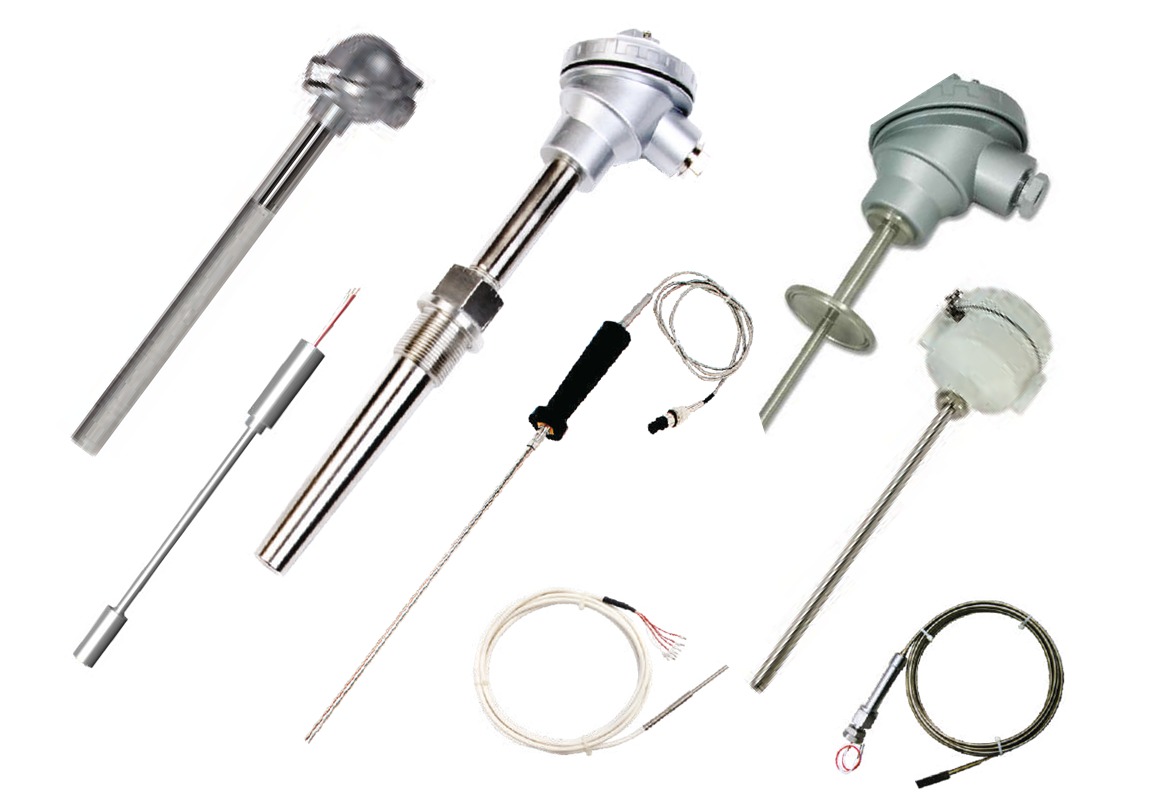
Resistance Temperature Detector (RTD)
Temperature measuring sensors which use the correlation between metal resistance and temperature to measure the temperature of a body. As metal temperature increase its electric resistance also get increase.
It means temperature of metal is directly proportional to metal resistance.
Metal Resistance can be:
R = R₀ (1+αt) t
R = Resistance of RTD at temperature t t
R₀ = Resistance of RTD at 0°C
α = Temperature coefficient of resistance
t = Temperature difference
How to choose right RTD:
There are many options to consider when choosing the correct RTD element for your requirements:
- Temperature range
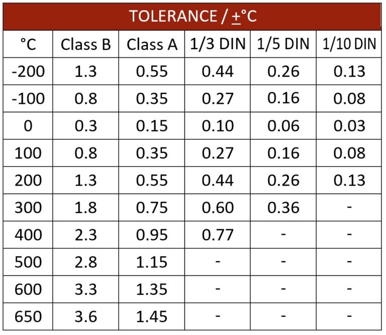
- Tolerance
- Accuracy
- Time response Vibrations
RTD Configuration:
The internal resistance of lead wire may significantly effect on accuracy of RTD. To deal with this problem, connection arrangements are available which compensate the lead wire internal resistance, these are shown below:
Two wire : There is no compensation for resistance of lead wires. Used where lead length is short.
Three wire : Typically connected to standard bridge circuit, which allows lead wire resistance to be compensated. Most common type of RTD assembly.
Four wire : Lead wire resistance errors are eliminated in this configuration by measuring the voltage across the RTD element supplied with a constant current. Recommended where higher accuracy is demanded.
RTD Specification
| Type | MI Type / Non MI Type |
| Configuration | Simplex / Duplex with 2 wire, 3 wire & 4 wire |
| Temperature Range | SPRT / SSPRT : - 200° to 850°C |
| Industrial : -200° C to 400°C | |
| Accuracy | Class A, Class B, DIN 1/3, DIN 1/5, DIN 1/10 |
| Enclosure Material | Die cast / SS316 / SS304 |
| Enclosure Approval | CCOE / ATEX / IP etc. |